
Page 442 - Chemical process engineering design and economics
P. 442
Design of Flow Systems 423
r FICJ
Flow Indicator Controller
FT ) Flow Transmitter x^-v Control Valve
'—i—J
-P4-*
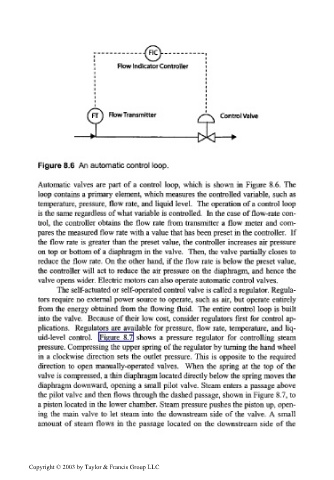
Figure 8.6 An automatic control loop.
Automatic valves are part of a control loop, which is shown hi Figure 8.6. The
loop contains a primary element, which measures the controlled variable, such as
temperature, pressure, flow rate, and liquid level. The operation of a control loop
is the same regardless of what variable is controlled. In the case of flow-rate con-
trol, the controller obtains the flow rate from transmitter a flow meter and com-
pares the measured flow rate with a value that has been preset in the controller. If
the flow rate is greater than the preset value, the controller increases air pressure
on top or bottom of a diaphragm hi the valve. Then, the valve partially closes to
reduce the flow rate. On the other hand, if the flow rate is below the preset value,
the controller will act to reduce the air pressure on the diaphragm, and hence the
valve opens wider. Electric motors can also operate automatic control valves.
The self-actuated or self-operated control valve is called a regulator. Regula-
tors require no external power source to operate, such as air, but operate entirely
from the energy obtained from the flowing fluid. The entire control loop is built
into the valve. Because of their low cost, consider regulators first for control ap-
plications. Regulators are available for pressure, flow rate, temperature, and liq-
uid-level control. Figure 8.7 shows a pressure regulator for controlling steam
pressure. Compressing the upper spring of the regulator by turning the hand wheel
in a clockwise direction sets the outlet pressure. This is opposite to the required
direction to open manually-operated valves. When the spring at the top of the
valve is compressed, a thin diaphragm located directly below the spring moves the
diaphragm downward, opening a small pilot valve. Steam enters a passage above
the pilot valve and then flows through the dashed passage, shown in Figure 8.7, to
a piston located in the lower chamber. Steam pressure pushes the piston up, open-
ing the main valve to let steam into the downstream side of the valve. A small
amount of steam flows in the passage located on the downstream side of the
Copyright © 2003 by Taylor & Francis Group LLC