
Page 446 - Chemical process engineering design and economics
P. 446
Design of Flow Systems 427
Reactarrt2
H——M—4P 1
(fp^ ——Safety Valve Coolant In
tx) On-Off Valve V^l^.^
M ThrotllinB Valve
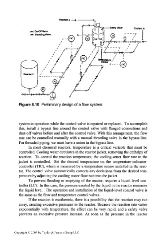
Figure 8.10 Preliminary design of a flow system.
system in operation while the control valve is repaired or replaced. To accomplish
this, install a bypass line around the control valve with flanged connections and
shut-off valves before and after the control valve. With this arrangement, the flow
rate can be controlled manually with a manual throttling valve in the bypass line.
For threaded piping, we must have a union in the bypass line.
In most chemical reactors, temperature is a critical variable that must be
controlled. Cooling water circulates in the reactor jacket, removing the enthalpy of
reaction. To control the reaction temperature, the cooling-water flow rate to the
jacket is controlled. Set the desired temperature on the temperature-indicator-
controller (TIC), which is measured by a temperature sensor installed in the reac-
tor. The control valve automatically corrects any deviations from the desired tem-
perature by adjusting the cooling-water flow rate into the jacket.
To prevent flooding or emptying of the reactor, requires a liquid-level con-
troller (LC). In this case, the pressure exerted by the liquid in the reactor measures
the liquid level. The operation and installation of the liquid-level control valve is
the same as the flow and temperature control valves.
If the reaction is exothermic, there is a possibility that the reaction may run
away, creating excessive pressures in the reactor. Because the reaction rate varies
exponentially with temperature, the effect can be very rapid, and a safety valve
prevents an excessive pressure increase. As soon as the pressure in the reactor
Copyright © 2003 by Taylor & Francis Group LLC