
Page 444 - Chemical process engineering design and economics
P. 444
Design of Flow Systems 425
D,rN? \
Steam Separator
T
Steam H— X 1 j\ 1 Ih 1 l*Vi?1 ii K^^« I H -
/ \ x Pressure Regulator
Strainer R
•» — - By-Pass ^.uiidensate
, Globe Valve
-1 ——————————————— 11- I/ ——————— h
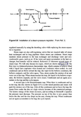
Figure 8.8 Installation of a steam-pressure regulator. From Ref. 3.
regulated manually by using the throttling valve while replacing the steam separa-
tor or regulator.
Steam traps are also self-regulating valves that are required after all steam
heat exchangers and in long pipelines where steam can condense. Steam traps
maintain steam pressure in the heat exchanger and discharge water and non-
condensable gases, such as air. If the water and gases accumulate in the heat ex-
changer, heat transfer will be reduced. Reference 22 discusses several types of-
steam traps. We will only discuss two types, which are shown in Figure 8.9. The
first type is a balanced-pressure thermostatic trap, which contains a bellows filled
with a liquid that evaporates when heated and condenses when cooled. As cool
condensate and air flows toward the trap, the vapor in the bellows condenses, the
bellows contracts, and the valve opens. Then, steam pushes the mixture of air and
water out of the trap. When steam reaches the trap, the liquid in the bellows evapo-
rates, the bellows expands, and the valve closes. Condensate and air again accu-
mulate in the trap and the cycle repeats.
A second type is the thermodynarnic trap. When there is condensate and air
in the trap, the disc shown in Figure 8.9 is in the raised position and steam will
push the mixture out of the trap. After all the condensate and air leave the trap, the
steam flows under the disc at a high velocity because of the constricted passage.
The kinetic energy of the steam increases, and according to Bernoulli's equation
the pressure must decrease. The pressure on top of the disc is now greater than
below the disc and the disc drops on the seat, closing the trap. When condensate
and air again accumulates in the trap, the cycle repeats.
Copyright © 2003 by Taylor & Francis Group LLC