
Page 445 - Chemical process engineering design and economics
P. 445
426 Chapter 8
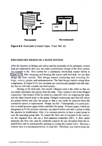
Thermostatic Thermodynamic
Figure 8.9 Examples of steam traps. From Ref. 22.
PRELIMINARY DESIGN OF A FLOW SYSTEM
After the function of fittings and valves and the principles of the automatic control
loop are understood, then you can make a preliminary design of the flow system.
An example is the flow system for a continuous stirred-tank reactor shown in
Figure 8.10. After designing and locating the reactor and feed tank, we can then
design the flow system. This design entails evaluating and selecting fit-
tings, valves, pumps, and instrumentation. The final design requires sizing these
components. In Figure 8.10, two reactants are continuously pumped into the reac-
tor, but we will only consider one feed system.
Starting at the feed tank, first install a flanged joint at the outlet so that we
can easily disconnect the piping from the tank. Then, connect a tee to the flanged
connection. One branch of the tee leads to a shut-off valve for emptying the tank,
and the other branch leads to the pump. Flanged connections and shut-off valves
are placed before and after the pump so that it can easily be removed from the
system for repairs or replacement. Pumps can fail. Consequently, it is good prac-
tice to install pressure gages before and after the pump. Pressure gages, which are
designated as PI for pressure indicator, are placed before and after a pump to help
the operator to troubleshoot. Also, it is common practice to have a spare pump in
case the operating pump fails. To control the flow rate of reactants to the reactor,
set the required flow rate on a flow-indicator-controller (FIC). A flow meter
measures the flow rate, and the controller corrects for any deviation from the re-
quired flow rate by automatically opening or closing the control valve. Because a
control valve is a mechanical device, it could fail. Therefore, you want to keep the
Copyright © 2003 by Taylor & Francis Group LLC