
Page 443 - Chemical process engineering design and economics
P. 443
424 Chapter 8
Pilot Valve
Steam Passage to
Upper Chamber
Steam Passage to Main Valve
Lower Chamber
Lower Chambei
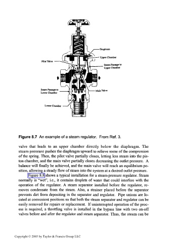
Figure 8.7 An example of a steam regulator. From Ref. 3.
valve that leads to an upper chamber directly below the diaphragm. The
steam pressure pushes the diaphragm upward to relieve some of the compression
of the spring. Then, the pilot valve partially closes, letting less steam into the pis-
ton chamber, and the main valve partially closes decreasing the outlet pressure. A
balance will finally be achieved, and the main valve will reach an equilibrium po-
sition, allowing a steady flow of steam into the system at a desired outlet pressure.
Figure 8.8 shows a typical installation for a steam-pressure regulator. Steam
normally is "wet", i.e., it contains droplets of water that could interfere with the
operation of the regulator. A steam separator installed before the regulator, re-
moves condensate from the steam. Also, a strainer placed before the separator
prevents dirt from depositing in the separator and regulator. Pipe unions are lo-
cated at convenient positions so that both the steam separator and regulator can be
easily removed for repairs or replacement. If uninterrupted operation of the proc-
ess is required, a throttling valve is installed in the bypass line with two on-off
valves before and after the regulator and steam separator. Thus, the steam can be
Copyright © 2003 by Taylor & Francis Group LLC