
Page 42 - Circuit Analysis II with MATLAB Applications
P. 42
Chapter 1 Second Order Circuits
Example 1.7
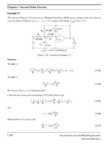
The circuit of Figure 1.19 a known as a Multiple Feed Back (MFB) active low-pass filter. For this cir-
cuit, the initial conditions are v C1 = v C2 = 0 . Compute and sketch v out t for t ! . 0
C 2 10 nF
R 2 40 K:
R 1 50 K:
+ v 1 v 2
200 K: R 3 +
v in v out
C 1 25 nF
v = 6.25cos 6280tu t
t
in
0
Figure 1.19. Circuit for Example 1.7
Solution:
At node :
v
1
v – v dv v – v v – v
in
out
1
1
1
1
2
----------------- + C -------- + -------------------- + --------------- = 0t ! 0 (1.83)
1
R 1 dt R 2 R 3
At node :
v
2
v – v dv out
--------------- = C ------------- (1.84)
2
1
R 3 2 dt
We observe that v = 0 (virtual ground).
2
Collecting like terms and rearranging (1.83) and (1.84) we get
dv
1
1
1
1
1 ·
§ ----- + ----- + ----- v + C -------- – -----v = -----v (1.85)
1
© R 1 R 2 R 3 ¹ 1 1 dt R 2 out R 1 in
and
dv
out
v = – R C ----------- (1.86)
1
2
3
dt
Differentiation of (1.86) yields
2
dv dv out
1
-------- = – R C ------------- (1.87)
3
dt 2 dt 2
1-30 Circuit Analysis II with MATLAB Applications
Orchard Publications