
Page 39 - Circuit Analysis II with MATLAB Applications
P. 39
Response of Parallel GLC Circuits with AC Excitation
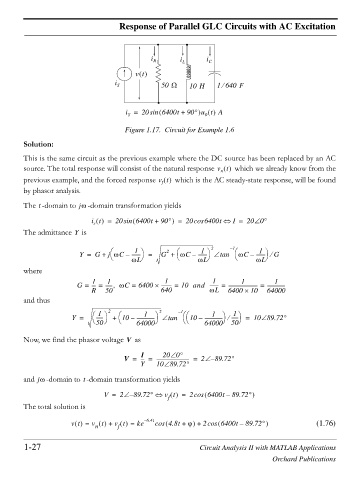
i R i L i C
vt `
i S 50 : 10 H 1640 F
e
i = 20sin 6400t + 90q u t A
0
S
Figure 1.17. Circuit for Example 1.6
Solution:
This is the same circuit as the previous example where the DC source has been replaced by an AC
source. The total response will consist of the natural response v t which we already know from the
n
previous example, and the forced response v t which is the AC steady-state response, will be found
f
by phasor analysis.
t
The -domain to jZ -domain transformation yields
i t = 20sin 6400t + 90q = 20cos 6400t I = 20 0q
s
Y
The admittance is
2 – 1
§
1 ·
1 ·
1 ·
2
Y = G + j ZC – ------- = G + § ZC – ------- tan § ZC – ------- e G
© ZL ¹ © ZL ¹ © ZL ¹
where
1
1
1
1
1
1
G = --- = ------ ZC =, 6400 u --------- = 10 and ------- = ------------------------ = ---------------
R 50 640 ZL 6400 u 10 64000
and thus
2
1
1
1
·
1 · §
·
Y = § ------ · 2 + § 10 – --------------- tan – 1 § 10 – --------------- e ------ = 10 89.72q
© 50 ¹ © 64000 ¹ © 64000 ¹ © 50 ¹
Now, we find the phasor voltage as
V
I 20 0q
V = --- = --------------------------- = 2 – 89.72q
Y 10 89.72q
t
and jZ -domain to -domain transformation yields
V = 2 – 89.72q v t = 2cos 6400t – 89.72q
f
The total solution is
vt = v t + v t = ke – 6.4t cos 4.8t + M + 2cos 6400t – 89.72q (1.76)
f
n
1-27 Circuit Analysis II with MATLAB Applications
Orchard Publications