Page 82 - Circuit Analysis II with MATLAB Applications
P. 82

Chapter 2  Resonance

         2.8 A Practical Parallel Resonant Circuit

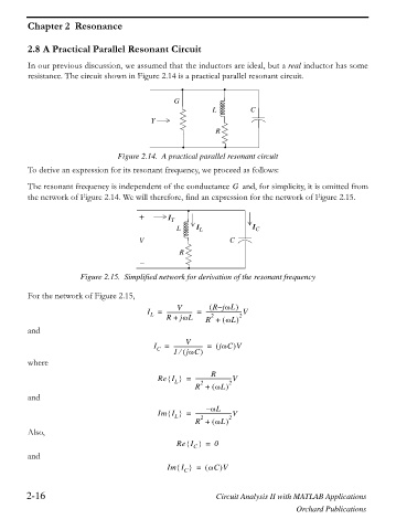
         In our previous discussion, we assumed that the inductors are ideal, but a real inductor has some
         resistance. The circuit shown in Figure 2.14 is a practical parallel resonant circuit.


                                                G
                                                           L  `      C
                                          Y
                                                            R


                                 Figure 2.14. A practical parallel resonant circuit
         To derive an expression for its resonant frequency, we proceed as follows:

         The resonant frequency is independent of the conductance   and, for simplicity, it is omitted from
                                                                G
         the network of Figure 2.14. We will therefore, find an expression for the network of Figure 2.15.

                                       +       I
                                                 L     I L            I C
                                                T `
                                       V                        C
                                                  R

                       Figure 2.15. Simplified network for derivation of the resonant frequency

         For the network of Figure 2.15,

                                                 V           RjZL   –
                                         I =  ------------------- =  ---------------------------V
                                          L
                                                                  2
                                                  jZL
                                                          2
                                              R +
                                                              ZL
                                                         R +


         and
                                                    V
                                           I C  =  --------------------- =     jZC   V
                                                    jZC  e
                                                1
         where
                                                          R
                                            Re I ^` =  ---------------------------V
                                                 L
                                                        2
                                                      R +     ZL    2
         and
                                                         – ZL
                                            Im I ^` =  ---------------------------V
                                                 L
                                                        2
                                                      R +     ZL    2
         Also,
                                                 Re I ^` =  0
                                                      C
         and
                                               Im I ^` =     ZC V

                                                   C
        2-16                                                Circuit Analysis II with MATLAB Applications
                                                                                  Orchard Publications
   77   78   79   80   81   82   83   84   85   86   87