
Page 84 - Circuit Analysis II with MATLAB Applications
P. 84
Chapter 2 Resonance
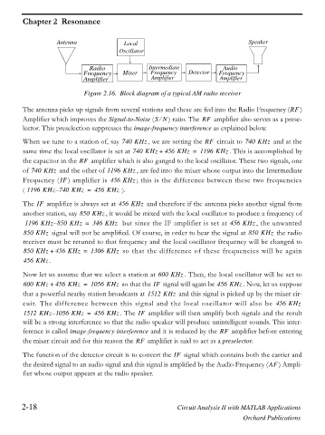
Antenna Local Speaker
Oscillator
Radio Intermediate Audio
Frequency Mixer Frequency Detector Frequency
Amplifier Amplifier Amplifier
Figure 2.16. Block diagram of a typical AM radio receiver
The antenna picks up signals from several stations and these are fed into the Radio Frequency (RF )
Amplifier which improves the Signal-to-Noise (SNe ) ratio. The RF amplifier also serves as a prese-
lector. This preselection suppresses the image-frequency interference as explained below.
When we tune to a station of, say 740 KHz , we are setting the RF circuit to 740 KHz and at the
same time the local oscillator is set at 740 KHz + 456 KHz = 1196 KHz . This is accomplished by
the capacitor in the RF amplifier which is also ganged to the local oscillator. These two signals, one
of 740 KHz and the other of 1196 KHz , are fed into the mixer whose output into the Intermediate
Frequency (IF ) amplifier is 456 KHz ; this is the difference between these two frequencies
( 1196 KHz 740– KHz = 456 KHz ).
The IF amplifier is always set at 456 KHz and therefore if the antenna picks another signal from
another station, say 850 KHz , it would be mixed with the local oscillator to produce a frequency of
–
1196 KHz 850 KHz = 346 KHz but since the IF amplifier is set at 456 KHz , the unwanted
850 KHz signal will not be amplified. Of course, in order to hear the signal at 850 KHz the radio
receiver must be retuned to that frequency and the local oscillator frequency will be changed to
850 KHz + 456 KHz = 1306 KHz so that the difference of these frequencies will be again
456 KHz .
Now let us assume that we select a station at 600 KHz . Then, the local oscillator will be set to
600 KHz + 456 KHz = 1056 KHz so that the IF signal will again be 456 KHz . Now, let us suppose
that a powerful nearby station broadcasts at 1512 KHz and this signal is picked up by the mixer cir-
cuit. The difference between this signal and the local oscillator will also be 456 KHz
–
1512 KHz 1056 KHz = 456 KHz . The IF amplifier will then amplify both signals and the result
will be a strong interference so that the radio speaker will produce unintelligent sounds. This inter-
ference is called image-frequency interference and it is reduced by the RF amplifier before entering
the mixer circuit and for this reason the RF amplifier is said to act as a preselector.
The function of the detector circuit is to convert the IF signal which contains both the carrier and
the desired signal to an audio signal and this signal is amplified by the Audio Frequency (AF ) Ampli-
fier whose output appears at the radio speaker.
2-18 Circuit Analysis II with MATLAB Applications
Orchard Publications