
Page 89 - Circuit Analysis II with MATLAB Applications
P. 89
Exercises
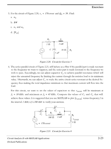
5. For the circuit of Figure 2.20, v = 170cos Zt and Q = 50 . Find:
0
s
a. Z 0
b. BW
c. Z 1 and Z 2
d. V C0
R 1 L
`
1 : 1 mH
C 10 : R 2
v s 1 PF
Figure 2.20. Circuit for Exercise 5
6. The series-parallel circuit of Figure 2.21, will behave as a filter if the parallel part is made resonant
to the frequency we want to suppress, and the series part is made resonant to the frequency we
wish to pass. Accordingly, we can adjust capacitor C 2 to achieve parallel resonance which will
reject the unwanted frequency by limiting the current through the resistive load to its minimum
value. Afterwards, we can adjust C 1 to make the entire circuit series resonant at the desired fre-
quency thus making the total impedance minimum so that maximum current will flow into the
load.
For this circuit, we want to set the values of capacitors so that v LOAD will be maximum at
f = 10 KHz and minimum at f = 43 KHz . Compute the values of C 1 and C 2 that will
2
1
f
achieve these values. It is suggested that you use MATLAB to plot v LOAD versus frequency in
f
the interval 1KHz dd 100 KH to verify your answers.
C 2
R L
C 1 1 ` + R
+ 100 : 2 mH L
v LOAD
v = 170cos Zt 1 :
S
Figure 2.21. Circuit for Exercise 6
Circuit Analysis II with MATLAB Applications 2-23
Orchard Publications