
Page 165 - Complete Wireless Design
P. 165
Amplifier Design
164 Chapter Three
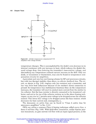
Figure 3.64 A diode temperature-compensated C-E
amplifier with voltage divider.
temperature changes. This is accomplished by the diode’s own decrease in its
internal resistance with any increase in heat, which reduces the diode’s for-
ward voltage drop, thus lowering the transistor’s base-emitter voltage, and
diminishing any temperature-induced current increase in the BJT. Only one
diode, or transistors or thermistors, may also be found in temperature com-
pensation circuits for amplifiers.
A prevalent and very low cost biasing scheme for RF and microwave circuits,
but with less thermal stability than above, is collector feedback bias. The cir-
cuit, as shown in Fig. 3.65, employs only two resistors and a transistor, and
has very little lead inductance because of the emitter’s direct connection to
ground. Its temperature bias stabilization functions thus: As the temperature
increases, the transistor will start to conduct more current from the emitter to
the collector. But the base resistor is directly connected to the transistor’s col-
lector, and not to the top of the collector resistor as in the above biasing tech-
niques, so any rise in I permits more voltage to be dropped across the collector
C
resistor. This forces less voltage to be dropped across the base resistor, which
decreases the base current and, consequently, I .
C
The discussion on active bias can be found in “Class A active bias for
microwave amplifiers” in Sec. 3.3.2.
FETs can utilize a common Class A biasing technique called source bias, a
form of self-bias (Fig. 3.66). With field-effect transistors, unlike bipolar junc-
tion transistors, no gate current will flow with an input signal present; so the
Downloaded from Digital Engineering Library @ McGraw-Hill (www.digitalengineeringlibrary.com)
Copyright © 2004 The McGraw-Hill Companies. All rights reserved.
Any use is subject to the Terms of Use as given at the website.