
Page 170 - Complete Wireless Design
P. 170
Amplifier Design
Amplifier Design 169
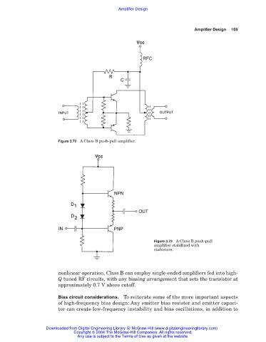
Figure 3.72 A Class B push-pull amplifier.
Figure 3.73 A Class B push-pull
amplifier stabilized with
stabistors.
nonlinear operation, Class B can employ single-ended amplifiers fed into high-
Q tuned RF circuits, with any biasing arrangement that sets the transistor at
approximately 0.7 V above cutoff.
Bias circuit considerations. To reiterate some of the more important aspects
of high-frequency bias design: Any emitter bias resistor and emitter capaci-
tor can create low-frequency instability and bias oscillations, in addition to
Downloaded from Digital Engineering Library @ McGraw-Hill (www.digitalengineeringlibrary.com)
Copyright © 2004 The McGraw-Hill Companies. All rights reserved.
Any use is subject to the Terms of Use as given at the website.