
Page 172 - Complete Wireless Design
P. 172
Amplifier Design
Amplifier Design 171
for even a single transistor model can be of a 10-to-1 range, with ß varia-
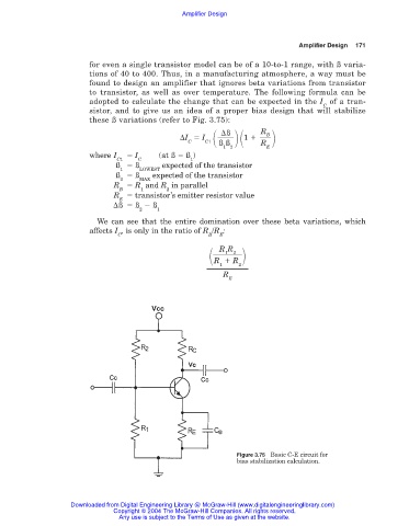
tions of 40 to 400. Thus, in a manufacturing atmosphere, a way must be
found to design an amplifier that ignores beta variations from transistor
to transistor, as well as over temperature. The following formula can be
adopted to calculate the change that can be expected in the I of a tran-
C
sistor, and to give us an idea of a proper bias design that will stabilize
these ß variations (refer to Fig. 3.75):
R
ß
B
I I C1 1
C ß ß R
1 2 E
where I I (at ß ß )
C1 C 1
ß ß expected of the transistor
1 LOWEST
ß ß expected of the transistor
2 MAX
R R and R in parallel
B 1 2
R transistor’s emitter resistor value
E
ß ß ß
2 1
We can see that the entire domination over these beta variations, which
affects I , is only in the ratio of R /R :
C B E
R R
1
2
R R
2
1
R
E
Figure 3.75 Basic C-E circuit for
bias stabilization calculation.
Downloaded from Digital Engineering Library @ McGraw-Hill (www.digitalengineeringlibrary.com)
Copyright © 2004 The McGraw-Hill Companies. All rights reserved.
Any use is subject to the Terms of Use as given at the website.