
Page 177 - Complete Wireless Design
P. 177
Amplifier Design
176 Chapter Three
3. Calculate I I /ß
B C
V V
BE
BB
4. Calculate R
B I
B
5. Calculate R V /I
1 BB BB
V V
C
BB
6. Calculate R
F I I
BB B
V V
CC
C
7. Calculate R
C I I I
C B BB
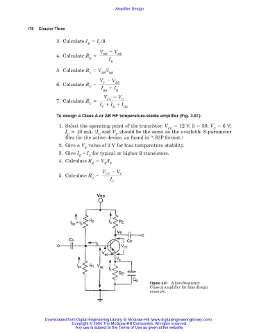
To design a Class A or AB HF temperature-stable amplifier (Fig. 3.81):
1. Select the operating point of the transistor: V 12 V; ß 50; V 6 V;
CC C
I 10 mA. (I and V should be the same as the available S-parameter
C C C
files for the active device, as found in *.S2P format.)
2. Give a V value of 2 V for bias temperature stability.
E
3. Give I ≈ I for typical or higher ß transistors.
E C
4. Calculate R V /I
E E E
V V
C
CC
5. Calculate R
C I
C
Figure 3.81 A low-frequency
Class A amplifier for bias design
example.
Downloaded from Digital Engineering Library @ McGraw-Hill (www.digitalengineeringlibrary.com)
Copyright © 2004 The McGraw-Hill Companies. All rights reserved.
Any use is subject to the Terms of Use as given at the website.