
Page 204 - Complete Wireless Design
P. 204
Amplifier Design
Amplifier Design 203
Operational amplifiers are far more common for voice-frequency amplifica-
tion for both low-level voltage signals and high-level power signals. They can
be acquired from many manufacturers, and are obtainable in an optimized sin-
gle-voltage supply package for ease of biasing.
3.7.2 Design of an IC audio amplifier
The National LM386 is a low-voltage audio amplifier that is perfect for low-
frequency amplification. In voiceband radios this IC can amplify the audio sig-
nal all the way from the detector stage to the 8-ohm speaker or headphones.
The National device has very low quiescent current drain (4 mA), accepts a
wide range of V (4 to 12 V), has adjustable voltage gain (20 to 200), decent
cc
distortion levels [ 10 percent total harmonic distortion (THD)], and has an
output driving power of 700 mW with a 9-V supply into 8 ohms.
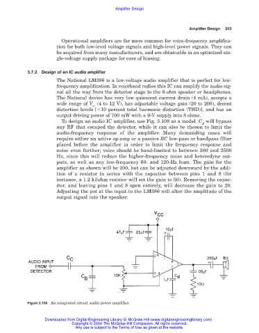
To design an audio IC amplifier, use Fig. 3.108 as a model. C will bypass
B
any RF that escaped the detector, while it can also be chosen to limit the
audio-frequency response of the amplifier. Many demanding cases will
require either an active op-amp or a passive RC low-pass or bandpass filter
placed before the amplifier in order to limit the frequency response and
noise even further; voice should be band-limited to between 300 and 2500
Hz, since this will reduce the higher-frequency noise and heterodyne out-
puts, as well as any low-frequency 60- and 120-Hz hum. The gain for the
amplifier as shown will be 200, but can be adjusted downward by the addi-
tion of a resistor in series with the capacitor between pins 1 and 8 (for
instance, a 1.2 kilohm resistor will set the gain to 50). Removing the capac-
itor, and leaving pins 1 and 8 open entirely, will decrease the gain to 20.
Adjusting the pot at the input to the LM386 will alter the amplitude of the
output signal into the speaker.
Figure 3.108 An integrated circuit audio power amplifier.
Downloaded from Digital Engineering Library @ McGraw-Hill (www.digitalengineeringlibrary.com)
Copyright © 2004 The McGraw-Hill Companies. All rights reserved.
Any use is subject to the Terms of Use as given at the website.