
Page 201 - Complete Wireless Design
P. 201
Amplifier Design
200 Chapter Three
capabilities (P IE) compared to a single-ended amplifier configuration.
Parallel amplifiers allow the entire parallel circuit to function as if it were a
single high-power transistor, at any bias desired (Class A, AB, B, and C).
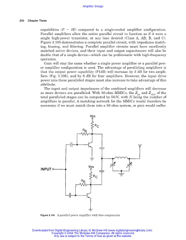
Figure 3.105 demonstrates a complete parallel circuit, with impedance match-
ing, biasing, and filtering. Parallel amplifier circuits must have excellently
matched active devices, and their input and output capacitances will also be
double that of a single device—which can be problematic with high-frequency
operation.
Gain will stay the same whether a single power amplifier or a parallel pow-
er amplifier configuration is used. The advantage of paralleling amplifiers is
that the output power capability (P1dB) will increase by 3 dB for two ampli-
fiers (Fig. 3.106), and by 6 dB for four amplifiers. However, the input drive
power into these paralleled stages must also increase to take advantage of this
attribute.
The input and output impedances of the combined amplifiers will decrease
as more devices are paralleled. With 50-ohm MMICs, the Z and Z of the
IN OUT
total paralleled stages can be computed by 50/N, with N being the number of
amplifiers in parallel. A matching network for the MMICs would therefore be
necessary if we must match them into a 50-ohm system, or gain would suffer.
Figure 3.105 A parallel power amplifier with bias components.
Downloaded from Digital Engineering Library @ McGraw-Hill (www.digitalengineeringlibrary.com)
Copyright © 2004 The McGraw-Hill Companies. All rights reserved.
Any use is subject to the Terms of Use as given at the website.