
Page 197 - Complete Wireless Design
P. 197
Amplifier Design
196 Chapter Three
of the amplifier—we want to be assured of stability at all frequencies. We can
do this by checking with our S parameters that the small-signal active device
will be unconditionally stable at all frequencies that are plotted within that
particular S-parameter file. This, however, will not include the very lowest of
frequencies, which are far below the measurements of most S-parameter files.
Huge instability problems internal to the amplifier can occur at frequencies
between 1 and 20 MHz, where the transistor’s gain can be as high as 40 dB.
This is mainly a problem with power amplifiers, but this high gain—combined
with even the slightest of internal or external in-phase feedback to the base—
will be an obvious recipe for oscillations. These oscillations are viewable on a
spectrum analyzer as a single carrier surrounded by sidebands; with the
injected carrier modulated by the low-frequency oscillations. So, we must find
a way to lessen either the gain or the feedback—or both—of the power ampli-
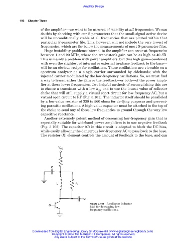
fier at these lower frequencies. Two helpful methods of accomplishing this are
to choose a transistor with a low h and to use the lowest value of collector
FE
choke that will still supply a virtual short circuit for low-frequency AC, but a
virtual open circuit to RF (Fig. 3.101). The inductor itself should be paralleled
by a low-value resistor of 330 to 560 ohms for de-Qing purposes and prevent-
ing parasitic oscillations. A high-value capacitor must be attached to the top of
the choke to send any of these low frequencies to ground through the very low
capacitive reactance.
Another extremely potent method of decreasing low-frequency gain that is
especially suitable for wideband power amplifiers is to use negative feedback
(Fig. 3.102). The capacitor (C) in this circuit is adopted to block the DC bias,
while easily allowing the dangerous low-frequency AC to pass back to the base.
The resistor (R) element controls the amount of feedback to the base, and can
Figure 3.101 A collector inductor
load for decreasing low-
frequency oscillations.
Downloaded from Digital Engineering Library @ McGraw-Hill (www.digitalengineeringlibrary.com)
Copyright © 2004 The McGraw-Hill Companies. All rights reserved.
Any use is subject to the Terms of Use as given at the website.