
Page 192 - Complete Wireless Design
P. 192
Amplifier Design
Amplifier Design 191
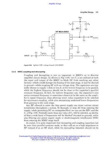
Figure 3.96 Agilent (HP) voltage-biased LNA MMIC.
3.4.3 MMIC coupling and decoupling
Coupling and decoupling is just as important in MMICs as in discrete
amplifier circuit design. As shown in Fig. 3.95, two C ’s are utilized at both
C
the input and output of the MMIC to block DC from reaching any other
devices—which would disrupt the biasing of the next stage, or just be shorted
to ground—while coupling RF with no voltage drop. The capacitors are typ-
ically chosen to supply 1 ohm or less X at the lowest frequency to be passed,
c
while the highest frequency should not be close to the capacitor’s parallel
resonant frequency. In fact, for narrow frequency use, the capacitor’s own
series-resonant frequency is sometimes chosen to be the same as the ampli-
fier’s signal frequency, thus allowing lower value capacitors to be selected
for microwave coupling, while also minimizing undesired lower frequencies
from passing to the next stage.
Any RF allowed to enter the bias power supply can cause various circuit
instabilities throughout a system. To decouple, or stop, AC from entering the
supply (while permitting DC an unimpeded flow) we can use the RFC and the
C of Fig. 3.95. Normally more than one value of C will be selected, as shown,
B B
so that a wide band of frequencies will be blocked (shunted to ground), while
also filtering any power supply ripple or electromagnetic interference (EMI)
from entering the MMIC stage itself.
As stated, it is quite important that decoupling and coupling capacitors not
be near their parallel-resonant mode, or they will act as a high impedance to
RF instead of as an RF short, while the decoupling inductors should not be
Downloaded from Digital Engineering Library @ McGraw-Hill (www.digitalengineeringlibrary.com)
Copyright © 2004 The McGraw-Hill Companies. All rights reserved.
Any use is subject to the Terms of Use as given at the website.