
Page 188 - Complete Wireless Design
P. 188
Amplifier Design
Amplifier Design 187
General Bias Notes
1. Utilization of an emitter resistor is avoided at VHF and above because its
small inductance would create instability and decrease gain. A stripline
opposed emitter (SOE) transistor package helps minimize this inductive
effect in the transistor’s leads themselves. However, some series lead induc-
tance will improve stability at lower frequencies. For instance, at 2 GHz an
inductance of up to 2 nH is good, but this value is usually present on the
bare emitter leads and the plated via hole to ground anyway.
2. The collector-to-base breakdown voltage of a transistor should be chosen to
be about 3 times its V .
CC
3. S will fall at 6 dB/octave in any active device, which translates into high
21
gain at low frequencies. This can mean low-frequency instability, necessi-
tating a gain flattening network in the transistor’s base circuit (See “Gain
Flattening” in Sec. 3.2.2).
3.4 MMICs
3.4.1 Introduction
MMICs are monolithic microwave integrated circuits, typically containing a
50-ohm small-signal amplifier that requires very few support components for
biasing, and none for impedance matching.
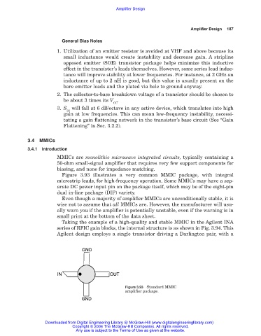
Figure 3.93 illustrates a very common MMIC package, with integral
microstrip leads, for high-frequency operation. Some MMICs may have a sep-
arate DC power input pin on the package itself, which may be of the eight-pin
dual in-line package (DIP) variety.
Even though a majority of amplifier MMICs are unconditionally stable, it is
wise not to assume that all MMICs are. However, the manufacturer will usu-
ally warn you if the amplifier is potentially unstable, even if the warning is in
small print at the bottom of the data sheet.
Taking the example of a high-quality and stable MMIC in the Agilent INA
series of RFIC gain blocks, the internal structure is as shown in Fig. 3.94. This
Agilent design employs a single transistor driving a Darlington pair, with a
Figure 3.93 Standard MMIC
amplifier package.
Downloaded from Digital Engineering Library @ McGraw-Hill (www.digitalengineeringlibrary.com)
Copyright © 2004 The McGraw-Hill Companies. All rights reserved.
Any use is subject to the Terms of Use as given at the website.