
Page 193 - Complete Wireless Design
P. 193
Amplifier Design
192 Chapter Three
close to any series-resonant modes, or they will begin to function as short cir-
cuits, and not as high impedances.
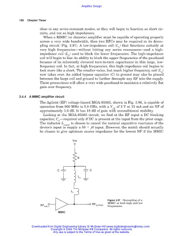
When a MMIC (or discrete) amplifier must be capable of operating properly
across a very wide bandwidth, then two RFCs may be required in its decou-
pling circuit (Fig. 3.97). A low-impedance coil (L ) that functions suitably at
1
very high frequencies—without hitting any series resonances—and a high-
impedance coil (L ) used to block the lower frequencies. The high-impedance
2
coil will begin to lose its ability to block the upper frequencies of the passband
because of its inherently elevated turn-to-turn capacitance in this large, low-
frequency coil. In fact, at high frequencies, this high-impedance coil begins to
look more like a short. The smaller-value, but much higher frequency, coil (L )
2
now takes over. An added bypass capacitor (C) to ground may also be placed
between the large coil and ground to further decouple any RF into the supply.
These precautions will allow a very wide passband to maintain a relatively flat
gain over frequency.
3.4.4 A MMIC amplifier circuit
The Agilent (HP) voltage-biased MGA-85563, shown in Fig. 3.96, is capable of
operation from 800 MHz to 5.8 GHz, with a V of 3 V at 15 mA and an NF of
CC
approximately 1.6 dB. It has 18 dB of gain with unconditional stability.
Looking at the MGA-85563 circuit, we find at the RF input a DC blocking
capacitor, C —required only if DC is present at the input from the prior stage.
C
The inductor L is chosen to cancel the natural capacitive reactance of the
match
device’s input to supply a 50 j0 input. However, the match should actually
be chosen to give optimum source impedance for the lowest NF if the MMIC
Figure 3.97 Decoupling of a
MMIC at both high and low
frequencies.
Downloaded from Digital Engineering Library @ McGraw-Hill (www.digitalengineeringlibrary.com)
Copyright © 2004 The McGraw-Hill Companies. All rights reserved.
Any use is subject to the Terms of Use as given at the website.