
Page 190 - Complete Wireless Design
P. 190
Amplifier Design
Amplifier Design 189
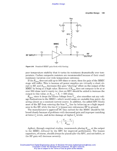
Figure 3.95 Standard MMIC gain block with biasing.
poor temperature stability that it varies its resistance dramatically over tem-
perature. Carbon composite resistors are recommended because of their small
resistance variation over wide temperature extremes.
If the R does not add up to 500 ohms or more, then the gain of the MMIC
BIAS
stage will suffer. This is because all power supplies are virtually a short cir-
cuit to RF, and R decreases this gain “shorting” effect on the output of the
BIAS
MMIC by being at a high value. However, if R does not compute to be at or
BIAS
over 500 ohms (and it rarely is), then an RFC should be added to increase the
output to this value, or R X 500 ohms.
BIAS L
R , since it drops the excess voltage from V , also smoothes out any volt-
BIAS CC
age fluctuations to the MMIC—which would cause an unstable bias point—by
acting almost as a constant current source. In addition, the added RFC blocks
most of the RF from entering the bias V line by behaving as a high imped-
CC
ance to the RF, while the two C ’s bypass any extraneous RF to ground.
B
The manufacturer’s approved DC bias current for the MMIC should be fol-
lowed closely because of problems with decreased gain and improper matching
at lower I levels, and device damage at higher I levels:
d d
d V CC V d
I
R
BIAS
Agilent, through empirical studies, recommends placing R at the output
BIAS
to the MMIC, followed by the RFC for improved performance. The bypass
capacitors, of course, should always be placed after the RFC, and not before, or
the RF gain will decrease severely.
Downloaded from Digital Engineering Library @ McGraw-Hill (www.digitalengineeringlibrary.com)
Copyright © 2004 The McGraw-Hill Companies. All rights reserved.
Any use is subject to the Terms of Use as given at the website.