
Page 186 - Complete Wireless Design
P. 186
Amplifier Design
Amplifier Design 185
ues of V and I . The I can be quoted as a percent of I —the maximum I —
ds d d dss d
such as “50 percent of I ,” which would work well for Class A bias.
dss
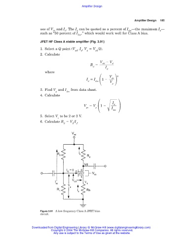
JFET HF Class A stable amplifier (Fig. 3.91)
1. Select a Q point (V , I , V V /2).
dd d d dd
2. Calculate
V V
d
dd
R
d I
d
where
V gs 2
I I 1
d dss V
p
3. Find V and I from data sheet.
p dss
4. Calculate
I
d
V V 1
gs p I dss
5. Select V to be 2 or 3 V.
s
6. Calculate R V /I .
S S d
Figure 3.91 A low-frequency Class A JFET bias
circuit.
Downloaded from Digital Engineering Library @ McGraw-Hill (www.digitalengineeringlibrary.com)
Copyright © 2004 The McGraw-Hill Companies. All rights reserved.
Any use is subject to the Terms of Use as given at the website.