
Page 200 - Complete Wireless Design
P. 200
Amplifier Design
Amplifier Design 199
V V
CC
C
1. R
BIAS I
C
2. Choose R to be between 5 and 10 ohms (the higher the R , the less gain).
e e
Z 2
0
3. R
f R
e
4. Z R R
0 f e
R
F
5. X ≈ at f
L P 8 MAX
X
L P
6. L
P 2 f
R R
e
f
7. V 20 log 10 (in a 50-ohm system)
GAIN 50 R
e
3.6 Parallel Amplifier
3.6.1 Introduction
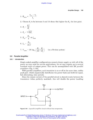
Single-ended amplifier configurations cannot always supply us with all of the
power we may need for certain applications, for we may require up to several
hundred watts of output power. This can be accomplished with RF parallel
amplifiers (Fig. 3.104).
With parallel amplifiers, each transistor is on or off at the same time, unlike
push-pull, which sequentially distributes the power back and forth for equal,
but alternating, time periods.
Since the output current of the parallel circuit is shared evenly between the
transistors (when perfectly matched), this will double the power handling
Figure 3.104 A parallel amplifier circuit without bias components.
Downloaded from Digital Engineering Library @ McGraw-Hill (www.digitalengineeringlibrary.com)
Copyright © 2004 The McGraw-Hill Companies. All rights reserved.
Any use is subject to the Terms of Use as given at the website.