
Page 199 - Complete Wireless Design
P. 199
Amplifier Design
198 Chapter Three
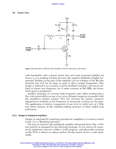
Figure 3.103 Resistive wideband RF amplifier with 50-ohm input and output.
wide bandwidth, with a decent return loss, and much increased stability. As
shown, L is a peaking coil that decreases the negative feedback at higher fre-
P
quencies, holding up the gain of the amplifier just as it begins to fall. But the
insertion loss will not be quite as good at these peaked frequencies. This
design is referred to as a resistive negative feedback amplifier, and can be uti-
lized at almost any frequency, but is more common at 600 MHz and below,
where gain is inexpensive.
Another technique to increase high-frequency gain while maintaining a
flat, wide bandwidth is to use a low value of bypass capacitor in parallel with
the amplifier’s emitter resistor. This will increase the emitter resistor’s
degenerative feedback as the frequency is decreased, leveling out the gain.
The application of emitter components of any kind is viable only at 2 GHz
and below because of the stability-robbing presence of their added lead
inductance.
3.5.2 Design of wideband amplifiers
Design of wideband LC matching networks for amplifiers is covered in detail
in Sec. 3.1.4, “Matching networks.”
The type of resistive ultrawideband amplifier discussed above (Fig. 3.103)
can initially be designed by the following formulas. It will need to be exten-
sively optimized, however, within a CAD program, and physically tweaked
on the PCB, to obtain an almost perfect 50-ohm match across a wide band-
width.
Downloaded from Digital Engineering Library @ McGraw-Hill (www.digitalengineeringlibrary.com)
Copyright © 2004 The McGraw-Hill Companies. All rights reserved.
Any use is subject to the Terms of Use as given at the website.