
Page 261 - Complete Wireless Design
P. 261
Frequency Synthesizer Design
260 Chapter Five
45 degrees, which is a good compromise between loop stability and loop
response.
T3/T1 percent. Normally chosen to be 45 percent. T3/T1 is the
ratio, expressed as a percentage, of the poles of the loop filter. The higher
this value (the closer to 100 percent) the more the reference spurs will be
attenuated; but peaking will begin to occur within the filter’s passband, and
R will increase in value, adding excessive thermal noise.
3
F MHz. The frequency of the reference oscillator before the R
REF
divider. Must be a multiple of F 10 MHz is a popular value, as applicable.
COM.
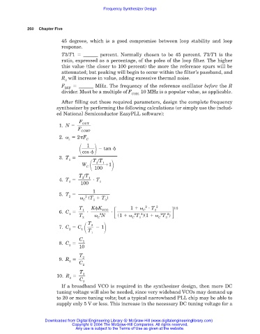
After filling out these required parameters, design the complete frequency
synthesizer by performing the following calculations (or simply use the includ-
ed National Semiconductor EasyPLL software):
F
OUT
1. N
F
COMP
2. 2 F
c C
tan
1
cos
3. T
1 T /T
1
3
W 1
C 100
T /T
3
4. T 1 T
3 1
100
1
5. T
2 2 (T T )
C 1 3
T K K 1 2 T 2 1/2
C
VCO
1
2
6. C
1 2 2 2 2 2
T N (1 T )(1 T )
2 C C 1 C 3
T
2
7. C C 1
2 1 T
1
C
1
8. C
3
10
T
2
9. R
2
C
2
T
3
10. R
3
C
3
If a broadband VCO is required in the synthesizer design, then more DC
tuning voltage will also be needed, since very wideband VCOs may demand up
to 20 or more tuning volts; but a typical narrowband PLL chip may be able to
supply only 5 V or less. This increase in the necessary DC tuning voltage for a
Downloaded from Digital Engineering Library @ McGraw-Hill (www.digitalengineeringlibrary.com)
Copyright © 2004 The McGraw-Hill Companies. All rights reserved.
Any use is subject to the Terms of Use as given at the website.