
Page 264 - Complete Wireless Design
P. 264
Frequency Synthesizer Design
Frequency Synthesizer Design 263
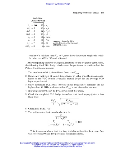
Figure 5.7 A popular high-
quality PLL chip, the National
LMX23XX series.
tenths of a volt less than V , so V must have the proper amplitude to ful-
p p
ly drive the VCO’s DC control input.)
After completing the filter’s design calculations for the frequency synthesizer,
the following final PLL design checks must be performed to confirm that the
PLL will function as desired:
1. The loop bandwidth f should be at least 1/20 F .
c COM
2. Make sure that C is at least 5 times larger in value than the input capac-
3
itance of the VCO (which is usually around 20 pF for the average VCO
input capacitance).
3. Since maximum PLL phase detector input frequencies normally are no
higher than 10 MHz, make sure that F is not above this amount.
COM
4. R must generally be set to divide by at least 3 or more.
5. Check the completed PLL design to confirm that the damping factor is less
than 1 by:
R C K K
2
VCO
2
2 )
N (C C C
3
2
1
6. Check that R /R
2.
3 2
7. The optimization index can be checked by:
T
2
1 ( T ) 2
C
2
T T 100
1
3
1 ( T ) 2 1 ( T ) 2
C 1 C 3
This formula confirms that the loop is stable with a fast lock time. Any
value between 90 and 100 percent is considered stable.
Downloaded from Digital Engineering Library @ McGraw-Hill (www.digitalengineeringlibrary.com)
Copyright © 2004 The McGraw-Hill Companies. All rights reserved.
Any use is subject to the Terms of Use as given at the website.