
Page 56 - Computational Retinal Image Analysis
P. 56
46 CHAPTER 3 The physics, instruments and modalities of retinal imaging
2
3D dataset needed to build a volume is in the order of 2.5 s (for 500 × 500 pixels
in the en-face plane), hence even if produced in real-time, a single en-face image is
produced 5 times slower than in en-face TD-OCT.
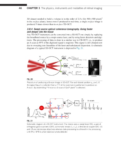
3.8.4 Swept source optical coherence tomography. Going faster
and deeper into the tissue
Any TD-OCT instrument can be converted into a SS-OCT one simply by replacing
the broadband source by a swept-source laser, and by using faster detectors and digi-
tizers. The processing of data is done in a similar way to CB-OCT, i.e., to produce
an A-scan an FFT of the digitized signal is required. This signal is still chirped now
due to sweeping non-linearities of the laser and unbalanced dispersion. A schematic
diagram of a typical SS-OCT instrument is depicted in Fig. 21.
FIG. 20
Procedure of producing a B-scan image in SD-OCT. For each lateral position x p , p = 1..P,
the signal I(xp,z) is collected then a FFT of the spectrum is performed to produce an
2
A-scan. By assembling P A-scans a B-scan of Q × P pixels is obtained.
FIG. 21
Schematic diagram of a SS-OCT instrument. The device uses a swept laser (SS), a pair of
orthogonal galvo-scanners (GXY), achromatic lenses (L 1 −L 2 ), a directional coupler (DC). LS
and LR are microscope objectives whereas data processing is achieved in the processing
unit (PU). BPD is a fast balanced photo-detector.