
Page 51 - Computational Retinal Image Analysis
P. 51
3 Ophthalmic instruments 41
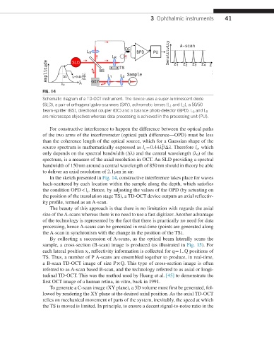
FIG. 14
Schematic diagram of a TD-OCT instrument. The device uses a super-luminescent diode
(SLD), a pair of orthogonal galvo-scanners (SXY), achromatic lenses (L 1 and L 2 ), a 50/50
beam-splitter (BS), directional coupler (DC) and a balance photo-detector (BPD). L S and L R
are microscope objectives whereas data processing is achieved in the processing unit (PU).
For constructive interference to happen the difference between the optical paths
of the two arms of the interferometer (optical path difference—OPD) must be less
than the coherence length of the optical source, which for a Gaussian shape of the
2
source spectrum is mathematically expressed as l c = 0.44λ 0 /Δλ. Therefore l c , which
only depends on the spectral bandwidth (∆λ) and the central wavelength (λ 0 ) of the
spectrum, is a measure of the axial resolution in OCT. An SLD providing a spectral
bandwidth of 150 nm around a central wavelength of 850 nm should in theory be able
to deliver an axial resolution of 2.1 μm in air.
In the sketch presented in Fig. 14, constructive interference takes place for waves
back-scattered by each location within the sample along the depth, which satisfies
the condition OPD < l c . Hence, by adjusting the values of the OPD (by actuating on
the position of the translation stage TS), a TD-OCT device outputs an axial reflectiv-
ity profile, termed as an A-scan.
The beauty of this approach is that there is no limitation with regards the axial
size of the A-scans whereas there is no need to use a fast digitizer. Another advantage
of the technology is represented by the fact that there is practically no need for data
processing, hence A-scans can be generated in real-time (points are generated along
the A-scan in synchronism with the change in the position of the TS).
By collecting a succession of A-scans, as the optical beam laterally scans the
sample, a cross-section (B-scan) image is produced (as illustrated in Fig. 15). For
each lateral position x i , reflectivity information is collected for q = 1..Q positions of
TS. Thus, a number of P A-scans are ensembled together to produce, in real-time,
a B-scan TD-OCT image of size P × Q. This type of cross-section image is often
referred to as A-scan based B-scan, and the technology referred to as axial or longi-
tudinal TD-OCT. This was the method used by Huang et al. [45] to demonstrate the
first OCT image of a human retina, in vitro, back in 1991.
To generate a C-scan image (XY plane), a 3D volume must first be generated, fol-
lowed by rendering the XY plane at the desired axial position. As the axial TD-OCT
relies on mechanical movement of parts of the system, inevitably, the speed at which
the TS is moved is limited. In principle, to ensure a decent signal-to-noise ratio in the