
Page 50 - Computational Retinal Image Analysis
P. 50
40 CHAPTER 3 The physics, instruments and modalities of retinal imaging
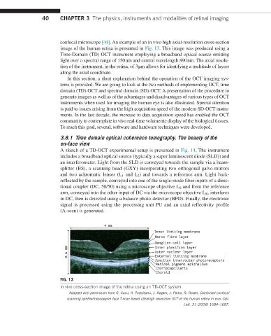
confocal microscope [44]. An example of an in vivo high axial-resolution cross-section
image of the human retina is presented in Fig. 13. This image was produced using a
Time-Domain (TD) OCT instrument employing a broadband optical source emitting
light over a spectral range of 150 nm and central wavelength 890 nm. The axial resolu-
tion of the instrument, in the retina, of 3 μm allows for identifying a multitude of layers
along the axial coordinate.
In this section, a short explanation behind the operation of the OCT imaging sys-
tems is provided. We are going to look at the two methods of implementing OCT, time
domain (TD)-OCT and spectral domain (SD)-OCT. A presentation of the procedure to
generate images as well as of the advantages and disadvantages of various types of OCT
instruments when used for imaging the human eye is also illustrated. Special attention
is paid to issues arising from the high acquisition speed of the modern SD-OCT instru-
ments. In the last decade, the increase in data acquisition speed has enabled the OCT
community to contemplate in vivo real-time volumetric display of the biological tissues.
To reach this goal, several, software and hardware techniques were developed.
3.8.1 Time domain optical coherence tomography. The beauty of the
en-face view
A sketch of a TD-OCT experimental setup is presented in Fig. 14. The instrument
includes a broadband optical source (typically a super luminescent diode (SLD)) and
an interferometer. Light from the SLD is conveyed towards the sample via a beam-
splitter (BS), a scanning head (GXY) incorporating two orthogonal galvo-mirrors
and two achromatic lenses (L 1 and L 2 ) and towards a reference arm. Light back-
reflected by the sample, conveyed into one of the single-mode fiber inputs of a direc-
tional coupler (DC, 50/50) using a microscope objective L S and from the reference
arm, conveyed into the other input of DC via the microscope objective L R , interferes
in DC, then is detected using a balance photo-detector (BPD). Finally, the electronic
signal is processed using the processing unit PU and an axial reflectivity profile
(A-scan) is generated.
FIG. 13
In vivo cross-section image of the retina using an TD-OCT system.
Adapted with permission from R. Cucu, A. Podoleanu, J. Rogers, J. Pedro, R. Rosen, Combined confocal
scanning ophthalmoscopy/en face T-scan based ultrahigh resolution OCT of the human retina in vivo, Opt.
Lett. 31 (2006) 1684–1687.