
Page 173 -
P. 173
152 3 Image processing
(a) (b) (c)
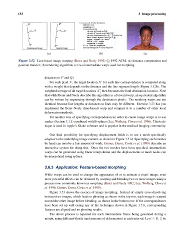
Figure 3.52 Line-based image warping (Beier and Neely 1992) c 1992 ACM: (a) distance computation and
position transfer; (b) rendering algorithm; (c) two intermediate warps used for morphing.
distances to P and Q).
For each pixel X, the target location X for each line correspondence is computed along
with a weight that depends on the distance and the line segment length (Figure 3.52b). The
weighted average of all target locations X then becomes the final destination location. Note
i
that while Beier and Neely describe this algorithm as a forward warp, an equivalent algorithm
can be written by sequencing through the destination pixels. The resulting warps are not
identical because line lengths or distances to lines may be different. Exercise 3.23 has you
implement the Beier–Neely (line-based) warp and compare it to a number of other local
deformation methods.
Yet another way of specifying correspondences in order to create image warps is to use
snakes (Section 5.1.1) combined with B-splines (Lee, Wolberg, Chwa et al. 1996). This tech-
nique is used in Apple’s Shake software and is popular in the medical imaging community.
One final possibility for specifying displacement fields is to use a mesh specifically
adapted to the underlying image content, as shown in Figure 3.51d. Specifying such meshes
by hand can involve a fair amount of work; Gomes, Darsa, Costa et al. (1999) describe an
interactive system for doing this. Once the two meshes have been specified, intermediate
warps can be generated using linear interpolation and the displacements at mesh nodes can
be interpolated using splines.
3.6.3 Application: Feature-based morphing
While warps can be used to change the appearance of or to animate a single image, even
more powerful effects can be obtained by warping and blending two or more images using a
process now commonly known as morphing (Beier and Neely 1992; Lee, Wolberg, Chwa et
al. 1996; Gomes, Darsa, Costa et al. 1999).
Figure 3.53 shows the essence of image morphing. Instead of simply cross-dissolving
between two images, which leads to ghosting as shown in the top row, each image is warped
toward the other image before blending, as shown in the bottom row. If the correspondences
have been set up well (using any of the techniques shown in Figure 3.51), corresponding
features are aligned and no ghosting results.
The above process is repeated for each intermediate frame being generated during a
morph, using different blends (and amounts of deformation) at each interval. Let t ∈ [0, 1] be