
Page 245 - Corrosion Engineering Principles and Practice
P. 245
220 C h a p t e r 7 221
The LA template of the locations that correspond to most likely
failure sites along tubes in a steam generator of a pressurized water
nuclear power plant (Fig. 7.8) is detailed in Table 7.4 for the main
failure modes and submodes considered in such analysis.
Maintenance and inspection actions can be decided upon by
following developing trends monitored in each LA matrix thus
produced.
The framework summarized in Table 7.3, which was initially
developed to predict the occurrence of stress corrosion cracking (SCC),
was extended to other corrosion modes/forms. Additionally, an
empirical correlation was established between the factors listed in
Table 7.3 and the forms of corrosion described earlier in Chap. 6.
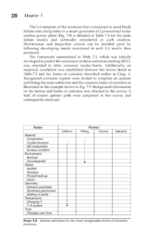
Recognized corrosion experts were invited to complete an opinion
poll listing the main subfactors and the common forms of corrosion as
illustrated in the example shown in Fig. 7.9. Background information
on the factors and forms of corrosion was attached to the survey. A
total of sixteen opinion polls were completed in this survey and
subsequently analyzed.
Factor Forms I
Uniform Pitting Crevice Galvanic
Material
Composition
Crystal structure
GB composition
Surface condition
Environment
Nominal
Circumstantial
Stress
Applied
Residual
Product built-up
Cyclic
Geometry
Galvanic potentials
Restricted geometries
Settling of solids
Temperature
Changing T
T of surface
Time
Changes over time
FIGURE 7.9 Opinion poll-sheet for the most recognizable forms of corrosion
problems.