
Page 255 - Corrosion Engineering Principles and Practice
P. 255
228 C h a p t e r 7 C o r r o s i o n F a i l u r e s , F a c t o r s , a n d C e l l s 229
Graphite
Platinum
Ni-Cr-Mo-Cu-Si alloy G
Ni-Cr-Mo alloy C
Titanium
Alloy 825
Alloy 20
316, 317 SS (passive)
Monel 400, K-500
Silver
302, 304, 321, 347 SS (passive)
Nickel 200
Silver bronze alloys
Alloy 600 (Passive)
Nickel-aluminium bronze
70–30 copper-nickel
Lead
430 SS (Passive)
80–20 copper-nickel
90–10 copper-nickel
Nickel silver
410, 416 SS (Passive)
Tin bronzes (G&M)
Silicon bronze
Manganese bronze
Admiralty, aluminium brasses
Pb-Sn Solder (50/50)
Copper
Tin
Naval, yellow, red brasses
Aluminium bronze
316, 317 SS (Active)
Alloy 600 (Active)
Austenitic nickel cast iron
302, 304, 321, 347 SS (Active)
410, 416, 430 SS (Active)
Low alloy steel
Mild steel, cast iron
Cadmium
Aluminium alloys
Zinc
Magnesium
–2 –1.5 –1 –0.5 0 0.5
Potential (V vs. SCE)
FIGURE 7.18 Galvanic series for slow-moving seawater.
However, the situation can lead to the corrosion of steel when the
surface area of the cathode (copper) approaches that of the anode (steel)
such as shown in Fig. 7.20 or when the surrounding environment is
more conductive or corrosive in the region where the galvanic coupling
exists (Fig. 7.21). In the example shown in Fig. 7.20, the anodic corrosion
of the anchor is partly due to the galvanic corrosion cell formed by the
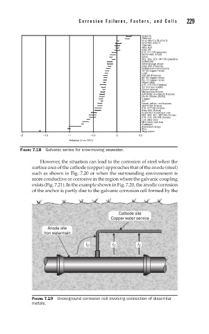
Cathode site
Copper water service
Anode site
Iron watermain
I C I C I C
FIGURE 7.19 Underground corrosion cell involving connection of dissimilar
metals.