
Page 92 - Corrosion Engineering Principles and Practice
P. 92
66 C h a p t e r 4 C o r r o s i o n T h e r m o d y n a m i c s 67
SHE AgCl SCE CuSO Hg SO HgO
4
4
2
(Standard) (Standard) (Saturated) (Saturated) (Saturated) (Standard)
1
1.2 1 1 0.6
0.8 0.2
1 0.8 0.8 0.4
0.6 0
0.8 0.6 0.6 0.2
0.4 –0.2
0.6 0.4 0.4 0
0.2 –0.4
0.4 0.2 0.2 –0.2
0 –0.6
0.2 0 0 –0.4
–0.2 –0.8
0 –0.2 –0.2 –0.6
–0.4 –1.0
–0.2 –0.4 –0.4 –0.8
–0.6 –1.2
–0.4 –0.6 –0.6 –1.0
–0.8 –1.4
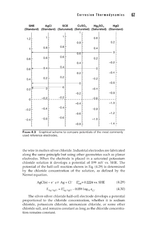
FIGURE 4.3 Graphical scheme to compare potentials of the most commonly
used reference electrodes.
the wire in molten silver chloride. Industrial electrodes are fabricated
along the same principle but using other geometries such as planar
electrodes. When the electrode is placed in a saturated potassium
chloride solution it develops a potential of 199 mV vs. SHE. The
potential of the half-cell reaction shown in Eq. (4.29) is determined
by the chloride concentration of the solution, as defined by the
Nernst equation.
AgCl(s) + e Ag + Cl − E red = 0.2224 vs. SHE (4.29)
−
0
E = E 0 − 0 05 9 log a − (4.30)
.
Ag/AgCl Ag/AgCl 10 Cl
The silver-silver chloride half-cell electrode develops a potential
proportional to the chloride concentration, whether it is sodium
chloride, potassium chloride, ammonium chloride, or some other
chloride salt, and remains constant as long as the chloride concentra-
tion remains constant.