
Page 339 - DSP Integrated Circuits
P. 339
324 Chapter 7 DSP System Design
has three sequential processes on the top level: input, FFT computation, and output.
The FFT consists of ten stages that are computed sequentially. Each stage contains
256 inner loops. We will later schedule the inner loops so that a new computation
can start every fourth memory clock cycle. The time interval between two succes-
sive inner loops is 125 ns. The inner loops will be mapped onto a pipelined hard-
ware structure with six stages. If the executions of two stages are not allowed to
overlap, we will need five extra loop cycles in each stage to empty the pipeline.
9
This means that the execution time of a stage will be (256 + 5) • 125 • 10~ = 32.625
us. The FFT computation consists of 10 stages. Hence, the execution time of the
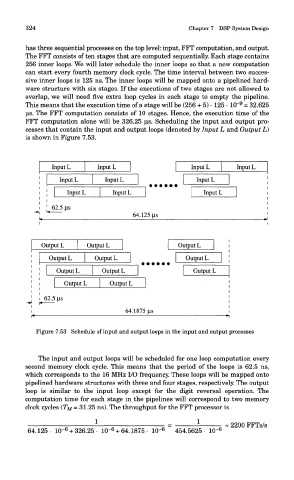
FFT computation alone will be 326.25 us. Scheduling the input and output pro-
cesses that contain the input and output loops (denoted by Input L and Output L)
is shown in Figure 7.53.
Figure 7.53 Schedule of input and output loops in the input and output processes
The input and output loops will be scheduled for one loop computation every
second memory clock cycle. This means that the period of the loops is 62.5 ns,
which corresponds to the 16 MHz I/O frequency. These loops will be mapped onto
pipelined hardware structures with three and four stages, respectively. The output
loop is similar to the input loop except for the digit reversal operation. The
computation time for each stage in the pipelines will correspond to two memory
clock cycles (TM = 31.25 ns). The throughput for the FFT processor is