
Page 343 - DSP Integrated Circuits
P. 343
328 Chapter 7 DSP System Design
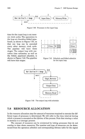
Figure 7.60 Processes in the input loop
time for the input loop is six mem-
ory clock cycles. The operations in
the loop are therefore folded (pipe-
lined), as shown in Figure 7.61, so
that one loop can be executed
every other memory clock cycle.
The pipeline will have three
stages. The output loop with exe-
cution time estimates, as well as
the folded, pipelined schedule, is
shown in Figure 7.62. The pipeline Figure 7.61 Schedule and folded schedule
will have four stages. for the input loop
Figure 7.62 The output loop with schedule
7.8 RESOURCE ALLOCATION
In the resource allocation step the amount of resources required to execute the dif-
ferent types of processes is determined. We will refer to the time interval during
which a process is executed as the lifetime of the process. Note that storing a value
in memory is a (storage) process.
The amount of resources can be minimized by letting processes that do not
overlap in time share resources. The number and type of resources can be deter-
mined from the operation schedule and corresponding lifetime table for the signal