
Page 37 - DSP Integrated Circuits
P. 37
22 Chapter 1 DSP Integrated Circuits
simulation, that the design problem is correctly captured. VHDL descriptions are
in practice also used as a communication medium between different design teams
and the manufacturer. In fact, some large customers—for example, the U.S.
Department of Defense—require a VHDL description of new circuits. The idea is
that the VHDL description can later be used in a redesign of the circuit using a
more advanced technology.
The VHDL language supports three main styles: behavioral, structural, and
data-flow descriptions. In all three styles, the basic unit is the design entity.
Design Entity A module is viewed as a design entity, which can be as simple as
a NAND gate or as complicated as a digital filter. The description of a design entity
in all three styles is divided into the interface description and one or more architec-
tural bodies. The use of design libraries is encouraged. The interface description
(port map) specifies the entity's connections with the external environment,
whereas the architectural body describes its function which can be described in
the three styles just mentioned.
Behavioral Description A pure behavioral description in the architectural
body is used for simulating functionality. However, it does not provide any direct
correspondence between the behavior and the real hardware.
Structural Description A structure is described by component declarations
and signal connections in terms of port maps. Components can be described as
being composed of lower-level components. Structural descriptions as well as data-
flow descriptions can be used for the synthesis of actual hardware.
Data-Flow Description The data-flow description is typically used to describe
the system as the flow of data between different units—for example, memories
and processing elements. Timing properties are taken into account by describing
signal waveforms. Functions to be performed are isolated in block declarations.
The activation of blocks is controlled by guarded statements. All signal assign-
ments transpire concurrently. The data-flow description is suitable for description
and simulation of signal-flow graphs.
We illustrate some of the basic concepts used in VHDL by the code for a full-
adder and a test bench that can be used to validate the code.
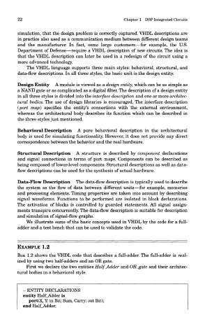
EXAMPLE 1.2
Box 1.2 shows the VHDL code that describes a full-adder. The full-adder is real-
ized by using two half-adders and an OR gate.
First we declare the two entities Half_Adder and OR_gate and their architec-
tural bodies in a behavioral style.
- ENTITY DECLARATIONS
entity Half_Adder is
port(X, Y: in Bit; Sum, Carry: out Bit);
end Half_Adder;