
Page 178 - Decision Making Applications in Modern Power Systems
P. 178
142 Decision Making Applications in Modern Power Systems
of system analysis tools for modeling this new scenario is required to
achieve a better comprehension of grid behaviors under different levels of
DG [30].
5.4.3 Harmonic studies
Loads play an important role in harmonic studies. Induction motors, synchro-
nous motors, and most commercial and residential loads present a linear
behavior, while electronic-based PC technologies are usually nonlinear loads
since they generate harmonics [31]. The following case is an example
of how aggregate linear load models impact harmonic studies, since their
type, magnitude, and composition may change the resonance conditions and
the voltage distortion in a power distribution system. Simulations were
performed in a COM environment involving OpenDSS and MATLAB.
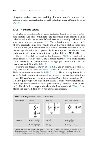
Three load models proposed in the literature [31,32] are analyzed—a
series model, a parallel model, and a model dedicated for a more specific
characterization of induction motors on an aggregated load. Their respective
parameters are indicated in Table 5.3.
The first test feeder is shown in Fig. 5.17, and an extension of this sys-
tem, with additional lines and loads connected, is displayed in Fig. 5.18.
Their parameters can be seen in Table 5.4 [33]. The source equivalent is the
same for both systems. Symmetrical parameters of power lines describe a
2
typical 185 mm primary network conductor. Power factor correction (PFC)
is a three-phase capacitor bank without losses. Current source represents har-
monic injection of electronic-based generation (e.g., inverters of PV genera-
tors). The dashed box represents where the load models of Table 5.3 are
placed and analyzed. Skin effect has not been considered.
TABLE 5.3 Aggregated linear load models.
Model type Series Parallel Induction motors
2
Parameters R 5 P P 2 1 Q 2 R 5 V P 2 R 5 ð1 2 KÞ P
2
V
V
V 2 V 2 V 2
X 5 Q X 5
P 2 1 Q 2 Q X 1 5 X M K m K P
P and Q are the active and reactive power, respectively; V is the rated line-to-line voltage, for a
three-phase system; K m is the install factor ( 1.2 p.u.); X M is the motor-locked rotor reactance
( 0.15 2 0.25 p.u.); and K is the fraction of motor load into the total load demand.