
Page 228 - Design and Operation of Heat Exchangers and their Networks
P. 228
Optimal design of heat exchangers 217
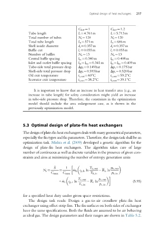
C RF ¼1 C RF ¼1.2
Tube length L¼4.761m L¼5.713m
Total number of tubes N t ¼120 N t ¼120
Total tube length L t ¼571m L t ¼686m
Shell inside diameter d s ¼0.357m d s ¼0.357m
Baffle cut l c ¼0.055m l c ¼0.055m
Number of baffles N b ¼13 N b ¼13
Central baffle spacing l bc ¼0.340m l bc ¼0.408m
Inlet and outlet baffle spacing l bi ¼l bo ¼0.341m l bi ¼l bo ¼0.409m
Tube-side total pressure drop Δp t ¼0.149bar Δp t ¼0.175bar
Shell-side total pressure drop Δp s ¼0.593bar Δp s ¼0.520bar
Oil exit temperature t s,out ¼60°C t s,out ¼59.2°C
Seawater exit temperature t t,out ¼38.2°C t t,out ¼39.1°C
It is important to know that an increase in heat transfer area (e.g., an
increase in tube length) for safety consideration might yield an increase
in tube-side pressure drop. Therefore, the constraints in the optimization
model should include the area enlargement case, as is shown in the
previously optimization model.
5.3 Optimal design of plate-fin heat exchangers
Thedesignofplate-finheatexchangersdealswithmanygeometricalparameters,
especially the fin types and fin parameters. Therefore, the design task shall be an
optimization task. Mishra et al. (2009) developed a genetic algorithm for the
design of plate-fin heat exchangers. The algorithm takes care of large
number of continuous as well as discrete variables in the presence of given con-
straints and aims at minimizing the number of entropy generation units
_ S 1 T h,out p h,out
N s ¼ ¼ _ m h c p,h ln R h ln
C max C max T h,in p h,in
T c,out p c,out
+ _m c c p,c ln R c ln (5.95)
T c,in p c,in
for a specified heat duty under given space restrictions.
The design task reads: Design a gas-to-air crossflow plate-fin heat
exchanger using offset-strip fins. The fin surfaces on both sides of exchanger
have the same specifications. Both the fluids are assumed to be air behaving
as ideal gas. The design parameters and their ranges are shown in Table 5.2.