
Page 229 - Design and Operation of Heat Exchangers and their Networks
P. 229
218 Design and operation of heat exchangers and their networks
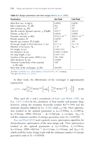
Table 5.2 Design parameters and their ranges (Mishra et al., 2009).
Parameters Hot fluid Cold fluid
Mass flow rate, _m (kg/s) 0.8962 0.8296
Inlet temperature, T in (K) 513 277
Inlet pressure, p in (Pa) 10 5 10 5
Specific isobaric thermal capacity, c p (J/kgK) 1017.7 1011.8
3
Density, ρ (kg/m ) 0.8196 0.9385
Dynamic viscosity, μ (sPa) 241.0 10 7a 218.2 10 7a
Prandtl number, Pr 0.6878 0.6954
Specific gas constant, R (J/kgK) 287 287
Exchanger length in flow direction, L (m) 0.1–1.0 0.1–1.0
1–10 N fl,h +1
Number of fin layers, N fl
Fin height, h f (m) 0.002–0.01
Fin thickness, δ f (m) 0.0001–0.0002
Fin strip length, l s (m) 0.001–0.01
Number of fins per meter, FPM (1/m) 100–1000
Plate thickness, δ p (m) 0.0008 b
Thermal conductivity of fin material, 150 b
λ f (W/mK)
Heat duty of the exchanger, Q (W) 160,000
a 7
In Table 1 of Mishra et al. (2009) and Rao and Patel (2010),10 is missing.
b
Not given by Mishra et al. (2009).
In their work, the effectiveness of the exchanger is approximately
expressed by
C max 0:22 C min 0:78
ε ¼ 1 exp NTU exp NTU 1 (5.96)
C min C max
They used the j and f correlations of Joshi and Webb (1987, see
Eqs. 3.275–3.280) for the calculation of heat transfer and pressure drop,
however, taking the transition Reynolds number Re*¼1500 and the
hydraulic diameter defined by Eq. (3.246) (with s ofs ¼δ f ). Their optimiza-
tion resulted in the optimal parameters as L h ¼0.994m, L c ¼0.887m,
1
h f ¼9.53mm, FPM¼534.9m , δ f ¼0.146mm, l s ¼6.3mm, N fl,h ¼8,
and the minimum number of entropy generation units N s ¼0.063332.
Rao and Patel (2010) used a particle swarm optimization algorithm for
thermodynamic optimization of the same design task. Their optimization
resulted in the optimal parameters as L h ¼0.925m, L c ¼0.996m,
1
h f ¼9.8mm, FPM¼442.9m , δ f ¼0.1mm, l s ¼9.8mm, and N fl,h ¼10,
which yield the better design result with the minimum number of entropy
generation units of N s ¼0.053028.