
Page 475 - Design and Operation of Heat Exchangers and their Networks
P. 475
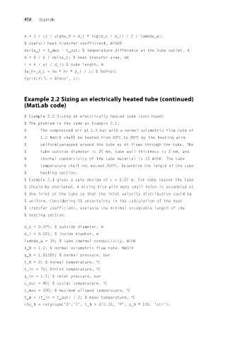
458   Appendix


          k =1/(1/ alpha_H + d_i ∗ log(d_o / d_i) / 2 / lambda_w);
          % overall heat transfer coefficient, W/m2K
          delta_t = t_max - t_out; % temperature difference at the tube outlet, K
          A =Q/k/ delta_t; % heat transfer area, m2
          L =A/pi/ d_i; % tube length, m
          Re_Pr_d_L = Re ∗ Pr ∗ d_i / L; % RePrd/L
          fprintf('L = %fm\n', L);


          Example 2.2 Sizing an electrically heated tube (continued)
          (MatLab code)

          % Example 2.2 Sizing an electrically heated tube (continued)
          % The problem is the same as Example 2.1:
          %     The compressed air at 1.5 bar with a normal volumetric flow rate of
          %     1.2 Nm3/h shall be heated from 20°Cto 80°C by the heating wire
          %     uniformlywrapped around the tube as it flows through the tube. The
          %     tube outside diameter is 25 mm, tube wall thickness is 2 mm, and
          %     thermal conductivity of the tube material is 15 W/mK. The tube
          %     temperature shall not exceed 200°C. Determine the length of the tube
          %     heating section.
          % Example 2.1 gives a safe design of L = 0.57 m. For some reason the tube
          % should be shortened. A mixing disk with many small holes is assembled at
          % the inlet of the tube so that the inlet velocity distribution could be
          % uniform. Considering 5% uncertainty in the calculation of the heat
          % transfer coefficient, evaluate the minimal acceptable length of the
          % heating section.

          d_o = 0.025; % outside diameter, m
          d_i = 0.021; % inside diamter, m
          lambda_w = 15; % tube thermal conductivity, W/mK
          V_N = 1.2; % normal volumetric flow rate, Nm3/h
          p_N = 1.01325; % normal pressure, bar
          t_N = 0; % normal temperature, °C
          t_in = 20; %inlet temperature, °C
          p_in = 1.5; % inlet pressure, bar
          t_out = 80; % outlet temperature, °C
          t_max = 200; % maximum allowed temperature, °C
          t_m = (t_in + t_out) / 2; % mean temperature, °C
          rho_N = refpropm('D','T', t_N + 273.15, 'P', p_N ∗ 100, 'air');