
Page 480 - Design and Operation of Heat Exchangers and their Networks
P. 480
Appendix 463
alpha_h = Nu_h ∗ lambda_h / d_i;
% tubeside heat transfer coefficient, W/m2K
s = kA / (N_tube ∗ pi ∗ d_i) ∗ (1 / alpha_h + R_w_i + d_i ...
/ (alpha_c ∗ d_o)) - L;
L=L+s;% calculated tube length, m
k_i = kA / (N_tube ∗ pi ∗ d_i ∗ L);
% overall heat transfer coefficient based on tubeside area, W/m2K
t_h_w_m = t_h_m - k_i ∗ (t_h_m - t_c_m) / alpha_h;
% mean wall temperature at hot water side (tubeside), °C
[cp_w, lambda_w, mu_w] = water_properties(t_h_w_m);
% viscosity at the tubeside wall, sPa
Pr_w = mu_w ∗ cp_w / lambda_w; % Prandtl number at the tubeside wall
if (abs(s) < 1E-6)
break;
end
end
fprintf('L = %fm\n', L);
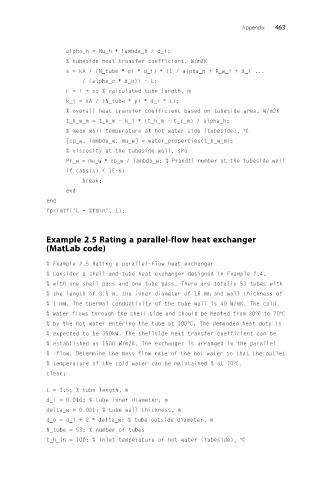
Example 2.5 Rating a parallel-flow heat exchanger
(MatLab code)
% Example 2.5 Rating a parallel-flow heat exchanger
% Consider a shell-and-tube heat exchanger designed in Example 2.4,
% with one shell pass and one tube pass. There are totally 53 tubes with
% the length of 3.5 m, the inner diameter of 16 mm and wall thickness of
% 1 mm. The thermal conductivity of the tube wall is 40 W/mK. The cold
% water flows through the shell side and should be heated from 20°Cto70°C
% by the hot water entering the tube at 100°C. The demanded heat duty is
% expected to be 350kW. The shellside heat transfer coefficient can be
% established as 1500 W/m2K. The exchanger is arranged in the parallel
% -flow. Determine the mass flow rate of the hot water so that the outlet
% temperature of the cold water can be maintained % at 70°C.
clear;
L = 3.5; % tube length, m
d_i = 0.016; % tube inner diameter, m
delta_w = 0.001; % tube wall thickness, m
d_o = d_i + 2 ∗ delta_w; % tube outside diameter, m
N_tube = 53; % number of tubes
t_h_in = 100; % inlet temperature of hot water (tubeside), °C