
Page 481 - Design and Operation of Heat Exchangers and their Networks
P. 481
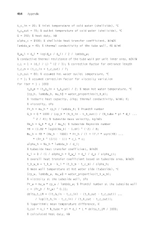
464   Appendix


          t_c_in = 20; % inlet temperature of cold water (shellside), °C
          t_c_out = 70; % outlet temperature of cold water (shellside), °C
          Q = 350; % heat duty, kW
          alpha_c = 1500; % shellside heat transfer coefficient, W/m2K
          lambda_w = 40; % thermal conductivity of the tube wall, 40 W/mK

          R_w_i = d_i ∗ log(d_o / d_i) / 2 / lambda_w;
          % conductive thermal resistance of the tube wall per unit inner area, m2K/W
          c_L = 1 + (d_i / L)  ^  (2 / 3); % correction factor for entrance length
          t_c_m = (t_c_in + t_c_out) / 2;
          t_h_out = 80; % assumed hot water outlet temperature, °C
          c = 1; % assumed correction factor for viscosity variation
          for iter = 1 : 1000
                t_h_m = (t_h_in + t_h_out) / 2; % mean hot water temperature, °C
                [cp_h, lambda_h, mu_h] = water_properties(t_h_m);
                % isobaric heat capacity, J/kg; thermal conductivity, W/mK; K;
                % viscosity, sPa
                Pr_h = mu_h ∗ cp_h / lambda_h; % Prandtl number
                G_h = Q ∗ 1000 / (cp_h ∗ (t_h_in - t_h_out)) / (N_tube ∗ pi ∗ d_i ...
                   ^
                     2 / 4); % tubeside mass velocity, kg/m2s
                Re_h = G_h ∗ d_i / mu_h; % tubeside Reynolds number
                f8 = (1.82 ∗ log10(Re_h) - 1.64)  ^  (-2) / 8;
                Nu_h = f8 ∗ (Re_h - 1000) ∗ Pr_h / (1 + 12.7 ∗ sqrt(f8) ...
                   ∗ (Pr_h  ^  (2/3) - 1)) ∗ c_L ∗ c;
                alpha_h = Nu_h ∗ lambda_h / d_i;
                % tubeside heat transfer coefficient, W/m2K
                k_i =1/(1/ alpha_h + R_w_i + d_i / d_o / alpha_c);
                % overall heat transfer coefficient based on tubeside area, W/m2K
                t_h_w_m = t_h_m - k_i ∗ (t_h_m - t_c_m) / alpha_h;
                % mean wall temperature at hot water side (tubeside), °C
                [cp_w, lambda_w, mu_w] = water_properties(t_h_w_m);
                % viscosity at the tubeside wall, sPa
                Pr_w = mu_w ∗ cp_w / lambda_w; % Prandtl number at the tubeside wall
                c = (Pr_h / Pr_w)  ^  0.11;
                delta_t_LM = ((t_h_in - t_c_in) - (t_h_out - t_c_out)) ...
                    / log((t_h_in - t_c_in) / (t_h_out - t_c_out));
                % logarithmic mean temperature difference, K
                Q_cal = k_i ∗ N_tube ∗ pi ∗ d_i ∗ L ∗ delta_t_LM / 1000;
                % calculated heat duty, kW