
Page 484 - Design and Operation of Heat Exchangers and their Networks
P. 484
Appendix 467
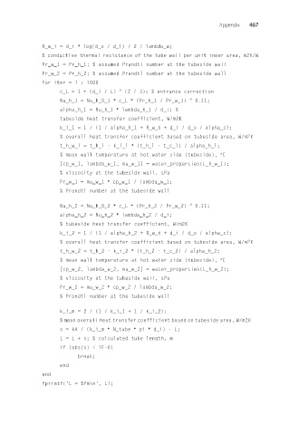
R_w_i = d_i ∗ log(d_o / d_i) / 2 / lambda_w;
% conductive thermal resistance of the tube wall per unit inner area, m2K/W
Pr_w_1 = Pr_h_1; % assumed Prandtl number at the tubeside wall
Pr_w_2 = Pr_h_2; % assumed Prandtl number at the tubeside wall
for iter = 1 : 1000
c_L = 1 + (d_i / L) ^ (2 / 3); % entrance correction
Nu_h_1 = Nu_h_0_1 ∗ c_L ∗ (Pr_h_1 / Pr_w_1) ^ 0.11;
alpha_h_1 = Nu_h_1 ∗ lambda_h_1 / d_i; %
tubeside heat transfer coefficient, W/m2K
k_i_1 =1/(1 / alpha_h_1 + R_w_i + d_i / d_o / alpha_c);
% overall heat transfer coefficient based on tubeside area, W/m2K
t_h_w_1 = t_h_1 - k_i_1 ∗ (t_h_1 - t_c_1) / alpha_h_1;
% mean wall temperature at hot water side (tubeside), °C
[cp_w_1, lambda_w_1, mu_w_1] = water_properties(t_h_w_1);
% viscosity at the tubeside wall, sPa
Pr_w_1 = mu_w_1 ∗ cp_w_1 / lambda_w_1;
% Prandtl number at the tubeside wall
Nu_h_2 = Nu_h_0_2 ∗ c_L ∗ (Pr_h_2 / Pr_w_2) ^ 0.11;
alpha_h_2 = Nu_h_2 ∗ lambda_h_2 / d_i;
% tubeside heat transfer coefficient, W/m2K
k_i_2 =1/(1 / alpha_h_2 + R_w_i + d_i / d_o / alpha_c);
% overall heat transfer coefficient based on tubeside area, W/m2K
t_h_w_2 = t_h_2 - k_i_2 ∗ (t_h_2 - t_c_2) / alpha_h_2;
% mean wall temperature at hot water side (tubeside), °C
[cp_w_2, lambda_w_2, mu_w_2] = water_properties(t_h_w_2);
% viscosity at the tubeside wall, sPa
Pr_w_2 = mu_w_2 ∗ cp_w_2 / lambda_w_2;
% Prandtl number at the tubeside wall
k_i_m =2/(1 / k_i_1 + 1 / k_i_2);
% mean overall heat transfer coefficient based on tubeside area, W/m2K
s = kA / (k_i_m ∗ N_tube ∗ pi ∗ d_i) - L;
L=L+s;% calculated tube length, m
if (abs(s) < 1E-6)
break;
end
end
fprintf('L = %fm\n', L);