
Page 485 - Design and Operation of Heat Exchangers and their Networks
P. 485
468 Appendix
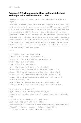
Example 2.7 Sizing a counterflow shell-and-tube heat
exchanger with baffles (MatLab code)
% Example 2.7 Sizing a counterflow shell-and-tube heat exchanger with
% baffles
% Consider a counterflow shell-and-tube heat exchanger with one shell pass
% and one tube pass. Hot water enters the tube at 100°C and leaves at 80°C.
% In the shellside, cold water is heated from 20°Cto70°C. The heat duty
% is expected to be 350 kW. There are totally 53 tubes with the inner
% diameter of 16 mm and wall thickness of 1 mm. The thermal conductivity of
% the tube wall is 40 W/mK. The shellside heat transfer coefficient can be
% established as 1500 W/m2K. The tubeside flow is assumed to be uniform,
% therefore Peh = ?. The shellside deviations from plug flow due to the
% baffles should be considered, with the baffle space ?L ? 0.5m. Calculate
% the tube length of the heat exchanger.
clear;
d_i = 0.016; % tube inner diameter, m
delta_w = 0.001; % tube wall thickness, m
d_o = d_i + 2 ∗ delta_w; % tube outside diameter, m
N_tube = 53; % number of tubes
delta_L = 0.5; % baffle space, m
Pe_h = Inf; % tubeside dispersive Peclet number
t_h_in = 100; % inlet temperature of hot water (tubeside), °C
t_h_out = 80; % outlet temperature of hot water (tubeside), °C
t_c_in = 20; % inlet temperature of cold water (shellside), °C
t_c_out = 70; % outlet temperature of cold water (shellside), °C
Q = 350; % heat duty, kW
alpha_c = 1500; % shellside heat transfer coefficient, W/m2K
lambda_w = 40; % thermal conductivity of the tube wall, 40 W/mK
t_h_m = (t_h_in + t_h_out) / 2;
[cp_h, lambda_h, mu_h] = water_properties(t_h_m);
% isobaric heat capacity, J/kg; thermal conductivity, W/mK; K; viscosity,
% sPa
Pr_h = mu_h ∗ cp_h / lambda_h; % Prandtl number
R_w_i = d_i ∗ log(d_o / d_i) / 2 / lambda_w;
% conductive thermal resistance of the tube wall per unit inner area, m2K/W
delta_t_LM = ((t_h_in - t_c_out) - (t_h_out - t_c_in)) ...
/ log((t_h_in - t_c_out) / (t_h_out - t_c_in));