
Page 84 - Design and Operation of Heat Exchangers and their Networks
P. 84
72 Design and operation of heat exchangers and their networks
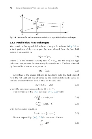
Fig. 3.1 Heat transfer and temperature variation in a parallel-flow heat exchanger.
3.1.1 Parallel-flow heat exchangers
We consider at first a parallel-flow heat exchanger. As is shown in Fig. 3.1,at
a local position of the exchanger, the heat released from the hot fluid
stream is represented by
_
dQ ¼ C h dt h (3.1)
_
_
where C is the thermal capacity rate, C ¼ _mc p , and the negative sign
indicates a temperature decrease along the coordinate z. The heat obtained
by the cold fluid stream is expressed as
_
dQ ¼ C c dt c (3.2)
According to the energy balance, in the steady state, the heat released
from the hot fluid and that obtained by the cold fluid should be equal to
the heat transferred from the hot fluid to the cold one:
dQ ¼ kA t h t c Þdz (3.3)
ð
where the dimensionless coordinate dz ¼ dA=A.
The substation of Eq. (3.3) into Eqs. (3.1), (3.2) yields
_ dt h
ð
C h ¼ kA t h t c Þ (3.4)
dz
_ dt c
ð
C c ¼ kA t h t c Þ (3.5)
dz
with the boundary condition
0
z ¼ 0 : t h ¼ t , t c ¼ t 0 (3.6)
h c
We can express Eqs. (3.4), (3.5) in the matrix form as
dT
¼ AT (3.7)
dz