
Page 403 - Design for Six Sigma a Roadmap for Product Development
P. 403
372 Chapter Ten
10.5.2 Pressure recorder PCB (printed-
circuit-board) replacement
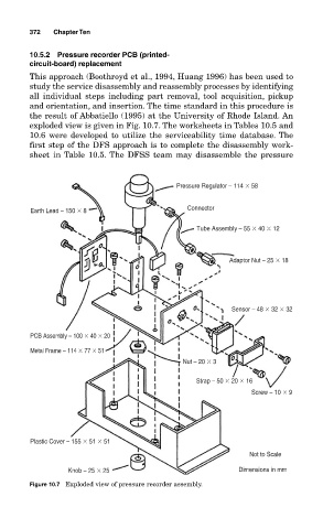
This approach (Boothroyd et al., 1994, Huang 1996) has been used to
study the service disassembly and reassembly processes by identifying
all individual steps including part removal, tool acquisition, pickup
and orientation, and insertion. The time standard in this procedure is
the result of Abbatiello (1995) at the University of Rhode Island. An
exploded view is given in Fig. 10.7. The worksheets in Tables 10.5 and
10.6 were developed to utilize the serviceability time database. The
first step of the DFS approach is to complete the disassembly work-
sheet in Table 10.5. The DFSS team may disassemble the pressure
Pressure Regulator – 114
58
Connector
Earth Lead – 150
8
Tube Assembly – 55
40
12
Adaptor Nut – 25
18
Sensor – 48
32
32
PCB Assembly – 100
40
20
Metal Frame – 114
77
51
Nut – 20
3
Strap – 50
20
16
Screw – 10
9
Plastic Cover – 155
51
51
Not to Scale
Knob – 25
25 Dimensions in mm
Figure 10.7 Exploded view of pressure recorder assembly.