Page 626 - Design for Six Sigma a Roadmap for Product Development
P. 626

Tolerance Design  579


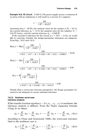
             Example 16.6. RL Circuit  A 100-V, f-Hz power supply across a resistance R
             in series with an inductance L will result in a current of y amperes:
                                            100
                                   y
                                        R   (2 fL )  2
                                           2
             Assuming that f   50 Hz, the nominal value for the resistor is T R   9.5  ,
             the current tolerance   R   1.0  , the nominal value for the inductor, T L
             0.01 H (henry), and the current tolerance   L   0.006 H.
               If the customer’s tolerance for the circuit is y   10.0    1.0 A, we would
             like to ascertain whether the design parameter tolerances are adequate.
             From Eqs. (16.2) and (16.3)
                                 100
             Max(y)   Max
                             R   (2 fL )  2
                               2
                                           100
                                                                     11.64
                       (9.5   1.0)   (2 
  3.1416 
 5 0 
 (0 .01   0.006))  2


                                 2
                                100
              Min(y)   Min
                             R   (2 fL )  2
                               2
                                           100
                                                                     8.59

                       (9.5   1.0)   (2 
  3.1416 
 5 0 
 (0 .01   0.006))  2


                                 2
                             100
                E(y)   E
                          R   (2 fL )  2
                            2
                                     100
                                                          9.99

                       (9.5)   (2 
  3.1416 
 50 
 (0 .01))  2

                            2
             Clearly, from a worst-case tolerance perspective, the design parameter tol-
             erance is not adequate to ensure customer tolerance.
           16.2.2 Nonlinear worst-case
           tolerance analysis
           If the transfer function equation y   f(x 1 ,x 2 ,…,x i ,…,x n ) is nonlinear, the
           tolerance analysis is difficult. From the Taylor expansion formula
           (Chap. 6) we obtain
                        ∂f        ∂f             ∂f            ∂f
                  y         x 1       x 2    ...        x i    ...        x n (16.4)
                       ∂x 1       ∂x 2          ∂x i          ∂x n
           According to Chase and Greenwood (1988), the worst-case tolerance
           limit in the nonlinear case is
                                           ...           ...
                                                               ∂f
                                   ∂f
                                                 ∂f
                         ∂f
                    0         1         2             i              n  (16.5)
                        ∂x 1      ∂x 2           ∂x i          ∂x n
   621   622   623   624   625   626   627   628   629   630   631