
Page 289 - Design of Simple and Robust Process Plants
P. 289
7.7 Site Vulnerability 275
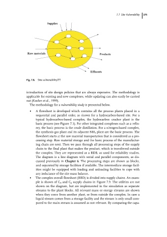
Supplies
Raw materials Products
Effluents
Fig. 7.8. Site vulnerablility???
introduction of site design policies that are always expensive. The methodology is
applicable for existing and new complexes, while updating can also easily be carried
out (Koolen et al., 1999).
The methodology for a vulnerability study is presented below.
. A flowsheet is developed which contains all the process plants placed in a
sequential and parallel order, as shown for a hydrocarbon-based site. For a
typical hydrocarbon-based complex, the hydrocarbon cracker plant is the
basic process (see Figure 7.1). For other integrated complexes such as a refin-
ery, the basic process is the crude distillation. For a nitrogen-based complex,
the synthesis gas plant and its adjacent NH 3 plant are the basic process. The
flowsheet starts at the raw material transportation that is considered as a pro-
cessing step. Raw material storage and the basic process of the manufactur-
ing chain are next. Then we pass through all processing steps of the supply
chain to the final plant that makes the product, which is transferred outside
the complex. They are represented as a RDB, as used for reliability studies.
The diagram is a line diagram with serial and parallel components, as dis-
cussed previously in Chapter 6. The processing steps are shown as blocks,
and separated by storage facilities if available. The intermediate storage facil-
ities might be equipped with loading and unloading facilities to cope with
any imbalance of the site mass balance.
. The complex overall flowsheet (RBD) is divided into supply chains. An exam-
ple is shown of C 4 and C 6 supply chains in Figure 7.9. The utilities are not
shown on the diagram, but are implemented in the simulation as separate
streams to the plant blocks. All relevant mass or energy streams are shown
when they come from another plant, or from outside the complex. In case a
liquid stream comes from a storage facility and the stream is only small com-
pared to the main stream is assumed as not relevant. By comparing the capa-