
Page 184 - Design of Solar Thermal Power Plants
P. 184
3.3 THERMAL PERFORMANCE OF PARABOLIC TROUGH COLLECTOR 169
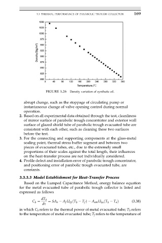
FIGURE 3.26 Density variation of synthetic oil.
abrupt change, such as the stoppage of circulating pump or
instantaneous change of valve opening control during normal
operation.
2. Based on all experimental data obtained through the test, cleanliness
of mirror surface of parabolic trough concentrator and exterior wall
surface of glazed shield tube of parabolic trough evacuated tube are
consistent with each other, such as cleaning these two surfaces
before the test.
3. For the connecting and supporting components at the glass-metal
sealing point, thermal stress buffer segment and between two
pieces of evacuated tubes, etc., due to the extremely small
proportions of their scales against the total length, their influences
on the heat-transfer process are not individually considered.
4. Profile defect and installation error of parabolic trough concentrator,
and positioning error of parabolic trough evacuated tube, are
constants.
3.3.3.3 Model Establishment for Heat-Transfer Process
Based on the Lumped Capacitance Method, energy balance equation
for the metal evacuated tube of parabolic trough collector is listed and
expressed as follows
dT b
C b ¼ ¼ SA a A f U bf ðT b T f Þ A am U ba ðT b T a Þ (3.38)
ds
in which C b refers to the thermal power of metal evacuated tube; T b refers
to the temperature of metal evacuated tube; T f refers to the temperature of