
Page 189 - Design of Solar Thermal Power Plants
P. 189
174 3. GENERAL DESIGN OF A SOLAR THERMAL POWER PLANT
In order to simplify the model, three constants are proposed, including
E 0 ¼ E r ðgsaÞ n (3.62)
(3.63)
E 1 ¼ E r ðgsaÞ a 1
n
E 2 ¼ E r ðgsaÞ a 2 (3.64)
n
Then three functions relevant to incidence angle are defined as:
f
I 0 ðqÞ¼ cosðqÞ 1 tanðqÞ (3.65)
L
f
I 1 ðqÞ¼ q 1 tanðqÞ (3.66)
L
2 f
I 2 ðqÞ¼ q 1 tanðqÞ (3.67)
L
Thus ES in Eq. (3.54) can be expressed as
ES ¼½E 0 I 0 ðqÞþ E 1 I 1 ðqÞþ E 2 I 2 ðqÞG DN (3.68)
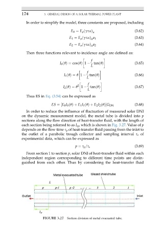
In order to reduce the influence of fluctuation of measured solar DNI
on the dynamic measurement model, the metal tube is divided into p
sections along the flow direction of heat-transfer fluid, with the length of
each section being referred to as L p , which is shown in Fig. 3.27. Value of p
depends on the flow time s p of heat-transfer fluid passing from the inlet to
the outlet of a parabolic trough collector and sampling interval s s of
experimental data, which can be expressed as
p ¼ s p =s s (3.69)
From section 1 to section p, solar DNI of heat-transfer fluid within each
independent region corresponding to different time points are distin-
guished from each other. Thus by considering the heat-transfer fluid
FIGURE 3.27 Section division of metal evacuated tube.